After our first class on earlier week, now we began to learn about assembly language.
During our lecture on Friday morning we have gone through a bit of tutorial about how to calculate a time consumption on a block of code using the 6502. For the lab 1 we were given to investigate a bit more complex code and do a more complex works on it.
First; As i understood, the lab is to use the 6502 Emulator and paste the Bitmap code below into the emulator as well.

When you disassemble this
Second; I will test the code by pressign the Assemble button and run them. Fix any occuring errors.
Third; I will calculate the performance (how long it takes to run the code) assuming a 1MHz clock speed and also calculate the memory usage.
Fourth; I will find one more more ways to optimize the code to reduce the time taken to fill the screen with a solid color.
Fifth; I will write a report about the lab and the results.
*hint: it should be nearly twice faster than the original code.
Sixth; Change the code to fill the display with light blue
Seventh; Change the code to fill the display with a different colour on each page
Eighth; Make each pixel a random color.
So let's begin:
As per the class lecture most of the 6502 runs in the 1Mhz clock speed. So that we are good to go with clock speed

First we see that we have lda #$00 and lda #$02 and lda #$07 before the loop.
Lets go ahead and write them down all the cycles from the 6502 Family CPU References.
<br>
Load Accumulator with Memory:
LDA #$nn is from Immediate Addressing Mode and have 2 Bytes each and 2 Cycles with Opcode of $A9.
Since the LDA #$nn immediate addressing instruction, it means that the processor fetches the instruction from memory which takes 1 cycle.
And loads the immediate value (#$nn) into the accumulator, which takes another 1 cycle.

Next we see that we have 2 STA including the LOOP.
Lets go ahead and write them down all the cycles from the 6502 Family CPU References as well.
STA is Store Accumulator in Memory and we have 2 different types of Assembly language form here.
One is STA$nn and the other is STA ($nn),y.
STA $nn is from Zero Page Addressing Mode and have 2 Bytes each and 3 Cycles with Opcode of $86.
STA ($nn),y is from Indirect Y- Indexed Addressing Mode and have 2 Bytes each and 5 Cycles with Opcode of $91.
STA $nn is from Zero Page Addressing which means that it's mode is in the range of $0000 to $00FF (the first 256 bytes of memory)
This instruction stores the value from the accumulator into a specific location within the Zero Page of memory.
It will fetch the instruction (reading the STA opcode from memory) that takes 1 cycle.
Then it will fetch the address (retrieve the zero page address $nn from memory) that takes another 1 cycle.
Finally it will store the Data to the specific memory location (write the accumulator value to the memory location of $nn) that takes another 1 cycle.
So total of 3 cycles for STA $nn.
STA ($nn),y is from Indirect Y- Indexed Addressing which means that it's mode is in the range of $0000 to $00FF (the first 256 bytes of memory) and indexed by Y register.
So similar to above it will fetch the base address ($nn) from memory then it will add the value of Y register to the base address($nn) and get to the final destination.
It will fetch the instruction (reading the STA opcode from memory) that takes 1 cycle.
Then it will fetch the Zero Page Address ($nn) from memory that retrieves the address $nn, that takes 1 cycle
Then it will fetch the 16-bit base address from Zero Page location $nn low byte and high byte $nn + 1, that takes 1 cycle
Then it will calculate the final address which means that it will add the Y register's value to the base address, that takes 1 cycle
Finally it will store the data by writing the accumulator's value to the calculated memory location, that takes 1 cycle
So total of 5 cycles, however if adding the Y register to the base address crosses a page boundary then it adds another 1 cycle. There fore total of 6 cycles will be added (Alt Cycle).

Now we have last one left before the loop. Which is ldy #$00.
LDY #$nn is Load Index Register Y and it is from Immediate Addressing Mode and have 2 Bytes each and 2 Cycles with Opcode of $A0.
And it has one cycle to fetch the instruction and another 1 cycle to load the immediate value into the Y-register.

Now we are going to write all the cycles after the loop in the middle of the table.
First we have iny which means Increment Index Register by One. It has one cycle to fetch the instruction and another 1 cycle to increment the Y register.
And we see that we have two bne loop, which we went over in class sample as well.
BNE means Branch if Not Equal and has 2 Bytes each and 2+t+p Cycles with Opcode of $D0.
And we go over from the class we can say that BNE loops have 2 cycles each but 3 cycles if the branch is taken.'
And we can see 3 other instructions which are inc $41, ldx $41 and cpx #$06
INC $nn is Increment Memory and has 2 Bytes each and 5 Cycles with Opcode of $E6.
LDX $nn is Load Index Register X and has 2 Bytes each and 3 Cycles with Opcode of $A6.
CPX #$nn is Compare Index Register X with Memory and has 2 Bytes each and 2 Cycles with Opcode of $E0.

So now here we complete the table for cycles and alt cycles.
Now lets go ahead and fill in "Count" column.

We do need to explain a bit further on this for the numbers that are a bit different than other ones like 4,1024,1020
Lets also take a look at our disassembly:
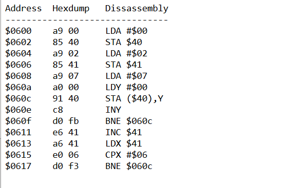
so the Inner Loop starts at 0 (LDY #$00)
INY increments Y by 1 each time and When Y becomes $00 again after $FF then it reaches the end and loop ends.
The loop excutes 256 times since it goes $00 to $FF and there are 4 pages, so 256 X 4 is 1024.
how about the BNE Loop that has 1020?
It has 255 times per page since Y is not 0 for those iterations so 255X 4 times is 1020 times.
Now we are almost close to final calculation but lets take a look again what we did because it seems
a bit off when we take a look at alt cycles and other columns. Some of them are wrongly inputted on cycles column for
a value of "taking branches" even if they were "not taking branches"
as well as for the inner bne loop we know now that it has 255 pixels and alt count will be 1X4 = 4 for the ending loop

So now its all done, lets do the calculation as professor said "this times this plus that times that"


So now in the end we get a total cycles of 11329 which is about 11 milliseconds.


No comments:
Post a Comment