Friday, January 17, 2025

Third Posting : Week 2 : end of Lab 1

This is second posting of the Lab 1, and we are finishing all the left overs for the lab 1.

6.Find one or more ways to decrease the time taken to fill the screen with a solid colour. Calculate the execution time of the fastest version of this program that you can create. Challenge: the fastest version is nearly twice as fast as the original version shown above!

Modifying the Code

7. Change the code to fill the display with light blue instead of yellow. (Tip: you can find the colour codes on the 6502 Emulator page).


Changed the color code of the lda#$07 to 

  • $6: Blue
  •   lda #$00 ; set a pointer in memory location $40 to point to $0200
      sta $40 ; ... low byte ($00) goes in address $40
      lda #$02
      sta $41 ; ... high byte ($02) goes into address $41
      lda #$e ; colour number change to blue
      ldy #$00 ; set index to 0
     loop: sta ($40),y ; set pixel colour at the address (pointer)+Y
      iny ; increment index
      bne loop ; continue until done the page (256 pixels)
      inc $41 ; increment the page
      ldx $41 ; get the current page number
      cpx #$06 ; compare with 6
      bne loop ; continue until done all pages


8. Change the code to fill the display with a different colour on each page (each “page” will be one-quarter of the bitmapped display).

        lda #$00        ; Set a pointer in memory location $40 to point to $0200
        sta $40         ; Low byte ($00) goes in address $40
        lda #$02        ; High byte ($02) for page $0200
        sta $41         ; Store high byte in $41
        lda #$02        ; Initial color number
        ldy #$00        ; Set index to 0

loop_pixel:
        sta ($40),y     ; Set pixel color at the address (pointer)+Y
        iny             ; Increment index
        bne loop_pixel  ; Continue until done with the page (256 pixels)

        inc $41         ; Increment the page
        adc #$01        ; Increment the color for the next page
        ldx $41         ; Get the current page number
        cpx #$06        ; Compare with 6
        bne loop_pixel  ; Continue until done all pages

        rts             ; Return from the program


9. Make each pixel a random colour. (Hint: use the psudo-random number generator mentioned on the 6502 Emulator page).

  • instead of using the fixed colour lda#$07 we use the pseudo random number generator mentioned on the Emulator page, which is lda #$fe
  • uses and #$0F to make sure the color stays the previously given code does not need any masking since it uses the fixed color schem.
  • More over we put the pseudo-random generator inside of the loop therefore we get all the pixels are different color.


        lda #$00        ; Set a pointer in memory location $40 to point to $0200
        sta $40         ; Low byte ($00) goes in address $40
        lda #$02        ; High byte ($02) for page $0200
        sta $41         ; Store high byte in $41
        lda #$02        ; Initial color number
        ldy #$00        ; Set index to 0

loop_pixel:
        sta ($40),y     ; Set pixel color at the address (pointer)+Y
        iny             ; Increment index
        bne loop_pixel  ; Continue until done with the page (256 pixels)

        inc $41         ; Increment the page
        adc #$01        ; Increment the color for the next page
        ldx $41         ; Get the current page number
        cpx #$06        ; Compare with 6
        bne loop_pixel  ; Continue until done all pages

        rts             ; Return from the program


"Good to know information before experiment"
In many old-school systems, the color of a pixel is not stored as a full 8-bit number but instead uses only a few bits (for example, 1 bits for 16 colors)

Experiments

Go back to the bitmap code above, and try these experiments:

  1. Add this instruction after the loop: label and before the sta ($40),y instruction: tya
  2. What visual effect does this cause, and how many colours are on the screen? Why?


tya is Transfer Y to A, copies current Y register value into the A register.
Since Y is incremented in the loop the pixel color will be based on Y coordinates instead of fixed color.
Striped effect with repeating colors, 32 strips total 1pixel each stripe


  1. Add this instruction after the tyalsr
  2. What visual effect does this cause, and how many colours are on the screen? Why?


When you use the Y‐value as the “seed” for the color and then shift it right, you’re effectively dividing its range by 2 for each LSR you add. In our code the Y register (which runs from 0 to 255) is “transferred” to A (via TYA) so that its bits determine the color.

However, because the video system only “sees” a limited number of color bits, the raw Y value already produces a repeating pattern of color “stripes” on screen. (In our experiment the unshifted value produces 32 narrow stripes.) When you add one LSR, you shift the bits one place right so that the effective colour value becomes Y÷2

this halves the number of distinct colors (and hence the number of repeating stripes) to 16.

  1. Repeat the above tests with two, three, four, and five lsr instructions in a row. Describe and explain the effect in each case.
-2 times


-3 times


-4 times


-5 times


So in each addition of the lsr we see that the "halving".
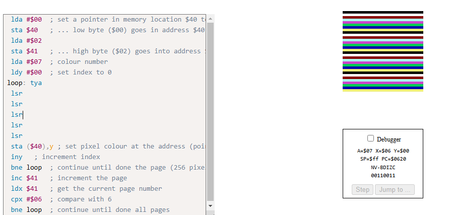
When Two lsr instructions : The value in A becomes  divided 4 (2^2)
So instead of 16 stripes that we had for the 1 lsr we are seeing 8 stripes.

When Three lsr instructions: The value in A becomes divided 8 (2^3)
So instead of 8 stripes that we had for the 2 lsr we are seeing 4strips

When Four lsr instructions: The value in A becomes divided 16 (2^4)
So instead of  4 stripes we see 2 stripes

When Fifth lsr instructions: The value in A becomes divided 32 (2^5)
So instead of  4 stripes we see 1 stripes with color expanded to right fully.


  1. Repeat the tests using asl instructions instead of lsr instructions. Describe and explain the effect in each case.
So now in this experiment we are using asl (Arithmetic Shift Left) instead of lsr. With the tya we ware doing Transfer Y to A and every ASL shifts A left on bit which means that we are doing A = (Y * 2^n) mod 256
Because the A register is 8 bits the result :wraps around" modulo 256 when it gets too high.

The value in A becomes the color of that pixel. On the emulator only a few bits of that values are used to pick palette color.

With one ASL: A = Y * 2 
The color value retains much of Y's original variation. seeing 8 distinct colors repeating 4 times. 32 stripes total.


With two ASL: A = Y * 4
The multiplication shifts out more bits, so many Y values now yield the same color. You see only 3 colors repeating 8 times.
With three ASL: A = Y * 8
Even more of the lower bits are lost. Only 2 distinct colors (including black) remain, repeating 16 times.

With four ASL: A = Y * 16
With five ASL: A = Y * 32

The multiplication wipes out all the variation in the lower nibble. Every pixel is computed to be 0 (black), so the entire display fills with black.


  1. Revert to the original code.

  2. The original code includes one iny instruction. Test with one to five consecutive iny instructions. Describe and explain the effect in each case. Note: it is helpful to place the Speed slider is on its lowest setting (left) for these experiments.
When there is one iny just like the original code, only one INY is excuted each time through the loop and Y goes from 0 to 255 in steps of 1. The entire 256 pixel page is filled sequentially with somekind of "ordered pattern"


When there are two iny like above image, Y will wrap to 0 after 128 iteration(256/2) and only half of addresses will be updated during this cycle, odd numbered addresses will be skipped. So we see that gaps as its stripe pattern.


When we run with 3 iny you start to see something a bit different but same result as one iny. When you run this instead of the yellow gets filled in ordered way it shows somewhat of different sequence order like visiting only odd numbers then fill others.

The values will go on 0, 3, 6... and so on. and since 3 and 256 are relatively prime adding 3 repeatedly will eventually hit every value in the 0-255 range but not in order(scrambled). 

When we run with 4 iny,Y increases by 4 each loop. and Y will take on values 0,4,8 and up to 252. and 4 will divide 256 evenly, the loop stops after only 64 iterations. As you can see from the above image, only one out of every four pixels is updated with stripe and res will show default background..


When we run with 5 iny we see that its all filled with yellow pixel but its a bit different then when we added only 3 iny. Y will increase by 5 each loop and will progress as 0, 5, 10, 15 and so on. And again 5 and 256 are relatively prime, it will repeatedly add by 5 and eventually cycle through all 256 values but in some different sequential order(scrambled).


No comments:

Post a Comment

10th Posting - Project: Stage 3

 Hello All! now we are on the final stage of the project which is project 3. If you remember correctly from my Stage 2 posting, i was able t...