Friday, January 17, 2025

Third Posting : Week 2 : end of Lab 1

This is second posting of the Lab 1, and we are finishing all the left overs for the lab 1.

6.Find one or more ways to decrease the time taken to fill the screen with a solid colour. Calculate the execution time of the fastest version of this program that you can create. Challenge: the fastest version is nearly twice as fast as the original version shown above!

Modifying the Code

7. Change the code to fill the display with light blue instead of yellow. (Tip: you can find the colour codes on the 6502 Emulator page).


Changed the color code of the lda#$07 to 

  • $6: Blue
  •   lda #$00 ; set a pointer in memory location $40 to point to $0200
      sta $40 ; ... low byte ($00) goes in address $40
      lda #$02
      sta $41 ; ... high byte ($02) goes into address $41
      lda #$e ; colour number change to blue
      ldy #$00 ; set index to 0
     loop: sta ($40),y ; set pixel colour at the address (pointer)+Y
      iny ; increment index
      bne loop ; continue until done the page (256 pixels)
      inc $41 ; increment the page
      ldx $41 ; get the current page number
      cpx #$06 ; compare with 6
      bne loop ; continue until done all pages


8. Change the code to fill the display with a different colour on each page (each “page” will be one-quarter of the bitmapped display).

        lda #$00        ; Set a pointer in memory location $40 to point to $0200
        sta $40         ; Low byte ($00) goes in address $40
        lda #$02        ; High byte ($02) for page $0200
        sta $41         ; Store high byte in $41
        lda #$02        ; Initial color number
        ldy #$00        ; Set index to 0

loop_pixel:
        sta ($40),y     ; Set pixel color at the address (pointer)+Y
        iny             ; Increment index
        bne loop_pixel  ; Continue until done with the page (256 pixels)

        inc $41         ; Increment the page
        adc #$01        ; Increment the color for the next page
        ldx $41         ; Get the current page number
        cpx #$06        ; Compare with 6
        bne loop_pixel  ; Continue until done all pages

        rts             ; Return from the program


9. Make each pixel a random colour. (Hint: use the psudo-random number generator mentioned on the 6502 Emulator page).

  • instead of using the fixed colour lda#$07 we use the pseudo random number generator mentioned on the Emulator page, which is lda #$fe
  • uses and #$0F to make sure the color stays the previously given code does not need any masking since it uses the fixed color schem.
  • More over we put the pseudo-random generator inside of the loop therefore we get all the pixels are different color.


        lda #$00        ; Set a pointer in memory location $40 to point to $0200
        sta $40         ; Low byte ($00) goes in address $40
        lda #$02        ; High byte ($02) for page $0200
        sta $41         ; Store high byte in $41
        lda #$02        ; Initial color number
        ldy #$00        ; Set index to 0

loop_pixel:
        sta ($40),y     ; Set pixel color at the address (pointer)+Y
        iny             ; Increment index
        bne loop_pixel  ; Continue until done with the page (256 pixels)

        inc $41         ; Increment the page
        adc #$01        ; Increment the color for the next page
        ldx $41         ; Get the current page number
        cpx #$06        ; Compare with 6
        bne loop_pixel  ; Continue until done all pages

        rts             ; Return from the program


"Good to know information before experiment"
In many old-school systems, the color of a pixel is not stored as a full 8-bit number but instead uses only a few bits (for example, 1 bits for 16 colors)

Experiments

Go back to the bitmap code above, and try these experiments:

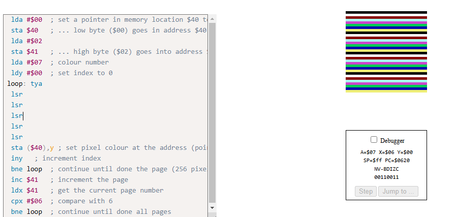
  1. Add this instruction after the loop: label and before the sta ($40),y instruction: tya
  2. What visual effect does this cause, and how many colours are on the screen? Why?


tya is Transfer Y to A, copies current Y register value into the A register.
Since Y is incremented in the loop the pixel color will be based on Y coordinates instead of fixed color.
Striped effect with repeating colors, 32 strips total 1pixel each stripe


  1. Add this instruction after the tyalsr
  2. What visual effect does this cause, and how many colours are on the screen? Why?


When you use the Y‐value as the “seed” for the color and then shift it right, you’re effectively dividing its range by 2 for each LSR you add. In our code the Y register (which runs from 0 to 255) is “transferred” to A (via TYA) so that its bits determine the color.

However, because the video system only “sees” a limited number of color bits, the raw Y value already produces a repeating pattern of color “stripes” on screen. (In our experiment the unshifted value produces 32 narrow stripes.) When you add one LSR, you shift the bits one place right so that the effective colour value becomes Y÷2

this halves the number of distinct colors (and hence the number of repeating stripes) to 16.

  1. Repeat the above tests with two, three, four, and five lsr instructions in a row. Describe and explain the effect in each case.
-2 times


-3 times


-4 times


-5 times


So in each addition of the lsr we see that the "halving".
When Two lsr instructions : The value in A becomes  divided 4 (2^2)
So instead of 16 stripes that we had for the 1 lsr we are seeing 8 stripes.

When Three lsr instructions: The value in A becomes divided 8 (2^3)
So instead of 8 stripes that we had for the 2 lsr we are seeing 4strips

When Four lsr instructions: The value in A becomes divided 16 (2^4)
So instead of  4 stripes we see 2 stripes

When Fifth lsr instructions: The value in A becomes divided 32 (2^5)
So instead of  4 stripes we see 1 stripes with color expanded to right fully.


  1. Repeat the tests using asl instructions instead of lsr instructions. Describe and explain the effect in each case.
So now in this experiment we are using asl (Arithmetic Shift Left) instead of lsr. With the tya we ware doing Transfer Y to A and every ASL shifts A left on bit which means that we are doing A = (Y * 2^n) mod 256
Because the A register is 8 bits the result :wraps around" modulo 256 when it gets too high.

The value in A becomes the color of that pixel. On the emulator only a few bits of that values are used to pick palette color.

With one ASL: A = Y * 2 
The color value retains much of Y's original variation. seeing 8 distinct colors repeating 4 times. 32 stripes total.


With two ASL: A = Y * 4
The multiplication shifts out more bits, so many Y values now yield the same color. You see only 3 colors repeating 8 times.
With three ASL: A = Y * 8
Even more of the lower bits are lost. Only 2 distinct colors (including black) remain, repeating 16 times.

With four ASL: A = Y * 16
With five ASL: A = Y * 32

The multiplication wipes out all the variation in the lower nibble. Every pixel is computed to be 0 (black), so the entire display fills with black.


  1. Revert to the original code.

  2. The original code includes one iny instruction. Test with one to five consecutive iny instructions. Describe and explain the effect in each case. Note: it is helpful to place the Speed slider is on its lowest setting (left) for these experiments.
When there is one iny just like the original code, only one INY is excuted each time through the loop and Y goes from 0 to 255 in steps of 1. The entire 256 pixel page is filled sequentially with somekind of "ordered pattern"


When there are two iny like above image, Y will wrap to 0 after 128 iteration(256/2) and only half of addresses will be updated during this cycle, odd numbered addresses will be skipped. So we see that gaps as its stripe pattern.


When we run with 3 iny you start to see something a bit different but same result as one iny. When you run this instead of the yellow gets filled in ordered way it shows somewhat of different sequence order like visiting only odd numbers then fill others.

The values will go on 0, 3, 6... and so on. and since 3 and 256 are relatively prime adding 3 repeatedly will eventually hit every value in the 0-255 range but not in order(scrambled). 

When we run with 4 iny,Y increases by 4 each loop. and Y will take on values 0,4,8 and up to 252. and 4 will divide 256 evenly, the loop stops after only 64 iterations. As you can see from the above image, only one out of every four pixels is updated with stripe and res will show default background..


When we run with 5 iny we see that its all filled with yellow pixel but its a bit different then when we added only 3 iny. Y will increase by 5 each loop and will progress as 0, 5, 10, 15 and so on. And again 5 and 256 are relatively prime, it will repeatedly add by 5 and eventually cycle through all 256 values but in some different sequential order(scrambled).


Tuesday, January 14, 2025

Second Posting : Week 1 : Calculating Cycles

After our first class on earlier week, now we began to learn about assembly language.

During our lecture on Friday morning we have gone through a bit of tutorial about how to calculate a time consumption on a block of code using the 6502. For the lab 1 we were given to investigate a bit more complex code and do a more complex works on it.


First; As i understood, the lab is to use the 6502 Emulator and paste the Bitmap code below into the emulator as well.


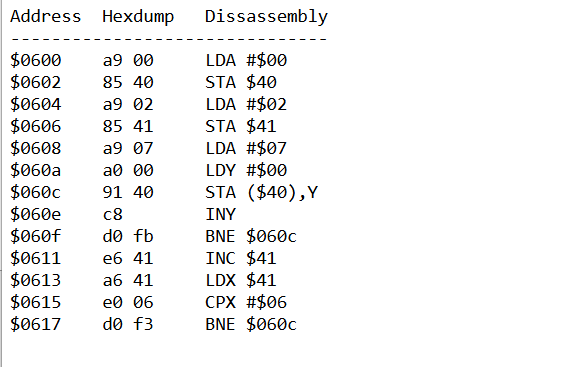
When you disassemble this

Second; I will test the code by pressign the Assemble button and run them. Fix any occuring errors.

Third; I will calculate the performance (how long it takes to run the code) assuming  a 1MHz clock speed and also calculate the memory usage.

Fourth; I will find one more more ways to optimize the code to reduce the time taken to fill the screen with a solid color.

Fifth; I will write a report about the lab and the results.

  *hint: it should be nearly twice faster than the original code.

Sixth; Change the code to fill the display with light blue

Seventh; Change the code to fill the display with a different colour on each page

Eighth; Make each pixel a random color.

So let's begin:

As per the class lecture most of the 6502 runs in the 1Mhz clock speed. So that we are good to go  with clock speed


First we see that we have lda #$00 and lda #$02 and lda #$07 before the loop.

Lets go ahead and write them down all the cycles from the 6502 Family CPU References.
<br>
Load Accumulator with Memory:

LDA #$nn is from Immediate Addressing Mode and have 2 Bytes each and 2 Cycles with Opcode of $A9.

Since the LDA #$nn immediate addressing instruction, it means that the processor fetches the instruction from memory which takes 1 cycle.

And loads the immediate value (#$nn) into the accumulator, which takes another 1 cycle.


Next we see that we have 2 STA including the LOOP.

Lets go ahead and write them down all the cycles from the 6502 Family CPU References as well.

STA is Store Accumulator in Memory and we have 2 different types of Assembly language form here.

One is STA$nn and the other is STA ($nn),y.

STA $nn is from Zero Page Addressing Mode and have 2 Bytes each and 3 Cycles with Opcode of $86.

STA ($nn),y is from Indirect Y- Indexed Addressing Mode and have 2 Bytes each and 5 Cycles with Opcode of $91.

STA $nn is from Zero Page Addressing which means that it's mode is in the range of $0000 to $00FF (the first 256 bytes of memory)

This instruction stores the value from the accumulator into a specific location within the Zero Page of memory.

It will fetch the instruction (reading the STA opcode from memory) that takes 1 cycle.

Then it will fetch the address (retrieve the zero page address $nn from memory) that takes another 1 cycle.

Finally it will store the Data to the specific memory location (write the accumulator value to the memory location of $nn) that takes another 1 cycle.

So total of 3 cycles for STA $nn.

STA ($nn),y is from Indirect Y- Indexed Addressing which means that it's mode is in the range of $0000 to $00FF (the first 256 bytes of memory) and indexed by Y register.

So similar to above it will fetch the base address ($nn) from memory then it will add the value of Y register to the base address($nn) and get to the final destination.

It will fetch the instruction (reading the STA opcode from memory) that takes 1 cycle.

Then it will fetch the Zero Page Address ($nn) from memory that retrieves the address $nn, that takes 1 cycle

Then it will fetch the 16-bit base address from Zero Page location $nn low byte and high byte $nn + 1, that takes 1 cycle

Then it will calculate the final address which means that it will add the Y register's value to the base address, that takes 1 cycle

Finally it will store the data by writing the accumulator's value to the calculated memory location, that takes 1 cycle

So total of 5 cycles, however if adding the Y register to the base address crosses a page boundary then it adds another 1 cycle. There fore total of 6 cycles will be added (Alt Cycle).


Now we have last one left before the loop. Which is ldy #$00.
LDY #$nn is Load Index Register Y and it is from Immediate Addressing Mode and have 2 Bytes each and 2 Cycles with Opcode of $A0.
And it has one cycle to fetch the instruction and another 1 cycle to load the immediate value into the Y-register.


Now we are going to write all the cycles after the loop in the middle of the table.

First we have iny which means Increment Index Register by One. It has one cycle to fetch the instruction and another 1 cycle to increment the Y register.

And we see that we have two bne loop, which we went over in class sample as well.
BNE means Branch if Not Equal and has 2 Bytes each and 2+t+p Cycles with Opcode of $D0.
And we go over from the class we can say that BNE loops have 2 cycles each but 3 cycles if the branch is taken.'

And we can see 3 other instructions which are inc $41, ldx $41 and cpx #$06
INC $nn is Increment Memory and has 2 Bytes each and 5 Cycles with Opcode of $E6.
LDX $nn is Load Index Register X and has 2 Bytes each and 3 Cycles with Opcode of $A6.
CPX #$nn is Compare Index Register X with Memory and has 2 Bytes each and 2 Cycles with Opcode of $E0.


So now here we complete the table for cycles and alt cycles.

Now lets go ahead and fill in "Count" column.


We do need to explain a bit further on this for the numbers that are a bit different than other ones like 4,1024,1020
Lets also take a look at our disassembly:

so the Inner Loop starts at 0 (LDY #$00)
INY increments Y by 1 each time and When Y becomes $00 again after $FF then it reaches the end and loop ends.
The loop excutes 256 times since it goes $00 to $FF and there are 4 pages, so 256 X 4 is 1024.

how about the BNE Loop that has 1020?
It has 255 times per page since Y is not 0 for those iterations so 255X 4 times is 1020 times.

Now we are almost close to final calculation but lets take a look again what we did because it seems a bit off when we take a look at alt cycles and other columns. Some of them are wrongly inputted on cycles column for a value of "taking branches" even if they were "not taking branches"

as well as for the inner bne loop we know now that it has 255 pixels and alt count will be 1X4 = 4 for the ending loop


So now its all done, lets do the calculation as professor said "this times this plus that times that"


So now in the end we get a total cycles of 11329 which is about 11 milliseconds.


Sunday, January 12, 2025

First Blogging for SPO 600 - Week 1

My First Encounter with Assembly Language

My first encounter with assembly language goes back to a game I played as a child—Roller Coaster Tycoon. Around 2005 or 2007, when I was just starting elementary school (or maybe a bit before), I used to play this game on my dad’s laptop, which ran Windows 98.

As I grew older and developed an interest in computer science, I started learning about programming languages—low-level, high-level, and everything in between. When I first saw what low-level languages looked like, my initial reaction was, “What is this alien language?”

Later, I learned that Roller Coaster Tycoon, the game I loved as a child, was created by a single developer over two years, entirely in a low-level language. The idea that a game this complex and beloved could be built using something so “alien” fascinated me.

At the time, I didn’t know much about how computers “talk.” I only knew how to communicate with them through layers of abstraction, like high-level programming languages. But with low-level languages, I realized I could get closer to the machine—closer to understanding how it really works.

Modern Programming Assumptions

As mentioned in the course notes, much of modern programming assumes that code will run on the target environment without requiring developers to think about the underlying architecture. High-level languages and frameworks abstract away much of the complexity, allowing us to write code that is portable across platforms.

However, not all code is portable. Some existing software contains architecture-specific code fragments, including assembly language. Such code assumes specific details about the hardware or environment and must be adapted—or "ported"—to work on other platforms.

Why Do We Need to Know Assembly Language?

Even in an age of high-level programming, assembly language remains an essential skill in certain scenarios. Here’s why:

1. Porting Software Across Architectures

Most software is designed to be portable, but some code relies on architecture-specific assumptions, such as memory layout, word size, or endianness. Often, these assumptions are embedded in low-level code, including assembly. To port such software:

  • Developers must understand assembly to rewrite or adapt these fragments for the target architecture.
  • This knowledge is crucial for translating performance-critical operations and handling platform-specific features.

2. Optimization and Performance Tuning

Optimization often requires decisions based on hardware architecture. Assembly provides:

  • Direct interaction with the CPU, enabling precise optimizations that compilers might overlook.
  • The ability to fine-tune atomic operations, optimize loops, or address edge-case floating-point behavior.

While modern compilers typically outperform hand-written assembly, certain performance-critical systems still benefit from manual assembly optimization.

3. Debugging and Diagnosing Low-Level Issues

Software doesn’t always behave as expected, particularly in performance-critical systems or during porting. Assembly knowledge helps developers:

  • Debug issues caused by compiler optimizations or low-level system behavior.
  • Diagnose hardware-related problems, such as incorrect memory ordering or unexpected CPU instructions.

4. Leveraging Platform-Specific Features

Certain hardware features, like CPUID registers or custom instructions, are only accessible through assembly. These are often needed for:

  • Performance benchmarking.
  • Profiling system behavior.
  • Controlling custom hardware.

5. Adapting to Emerging Architectures

New architectures like AArch64 and RISC-V are gaining traction:

  • AArch64, a 64-bit ARM architecture, is widely adopted but still undergoing optimization compared to x86_64.
  • RISC-V, an open-source architecture, offers flexibility but requires developers to handle low-level details for optimization.

Assembly knowledge enables developers to contribute to these emerging ecosystems by writing or optimizing software for these platforms.

6. Building Software and Ensuring Optimization

The software build process involves stages like assembling and linking, where low-level assembly code is generated. Understanding this process allows developers to:

  • Optimize builds for specific performance needs, such as memory usage or execution speed.
  • Ensure accurate benchmarks and profiling that reflect real-world scenarios.

7. Profiling and Identifying Bottlenecks

Profiling involves analyzing resource usage, such as memory, CPU cycles, or power, at a granular level. Assembly knowledge helps developers:

  • Pinpoint inefficiencies in specific functions or processes.
  • Rework performance-critical code to improve overall efficiency.

Conclusion

Looking back, my fascination with Roller Coaster Tycoon sparked my curiosity about assembly language and low-level programming. Even today, it’s incredible to think that this game was crafted using such a challenging language.

As developers, we often rely on high-level tools to bridge the gap between us and the machine. But learning assembly allows us to step closer—closer to understanding how computers think and how we can optimize and adapt software for their unique architectures. It’s a skill that not only deepens our understanding but also equips us to tackle challenges in porting, optimization, and debugging.

In a way, assembly language is like learning the native tongue of the computer. And as I continue to learn and grow, I’m reminded of how this “alien language” once seemed impossible to grasp but now feels like a key to unlocking new possibilities in software development.

10th Posting - Project: Stage 3

 Hello All! now we are on the final stage of the project which is project 3. If you remember correctly from my Stage 2 posting, i was able t...